
The press brake tonnage is mainly determined by factors such as material thickness, length, material type and bending angle. The commonly used formula is to calculate the required bending force based on the bending moment and material tensile strength, and then determine the tonnage of the bending machine.
Generally, the CNC press brake tonnage calculation can be according to the following table, and set in the processing parameters.
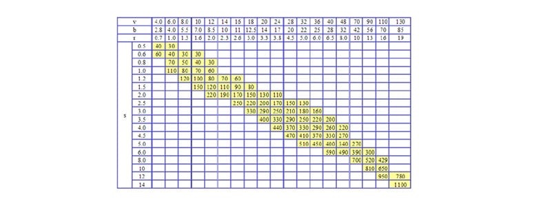
Press Brake Tonnage Calculation Chart
The value in the table is the bending pressure when the sheet length is 1m.
For example: S=4mm, L=1000mm, V=32mm, check the table to get P=330KN.
This table is calculated based on the material strength of σb=450N/mm2.
When bending other different materials, the bending pressure is the product of the data in the table and the following coefficients:
– Bronze (soft): 0.5
– Stainless steel: 1.5
– Aluminum (soft): 0.5
– Chrome-molybdenum steel: 2.0
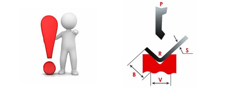
P=650S2L/V (σb=450MPa)
– P: Bending Force(Kn)
– S: Thickness of the Plate (mm)
– L: Width of the Plate (mm)
– V: V-Opening of the Bottom Die(mm)
Actual tonnage is affected by many factors, This formula calculates the press brake force requirement for air bending, it’s better that our machine actual force allow for up to 20% additional capacity.
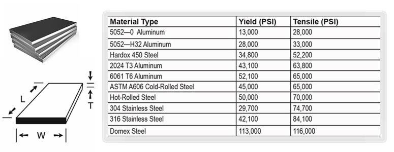
The tensile strength of a metal sheet refers to the maximum stress that the material can withstand when subjected to tension, and the unit is usually megapascal (MPa).
It is one of the important indicators of the mechanical properties of the material, which directly affects the performance and machinability of the material. The tensile strength can be measured by the stress-strain curve of the material, usually in a standard tensile test.
Tensile strength refers to the maximum stress value that a metal material can withstand during a tensile test, from the application of external force to the fracture process.
The formula is:
σb =Fmax/A0
- σb is the tensile strength (MPa)
- Fmax is the maximum tensile force (N) that the specimen can withstand when it breaks.
- A0 is the original cross-sectional area of the sample (mm²)
The tensile strength of different types of metal materials varies greatly and is affected by the following factors:
- Material type:
The atomic structure, alloy composition, grain size, etc. of the metal will affect the tensile strength.
- Heat treatment:
Annealing, quenching, tempering and other process treatments will change the crystal structure of the metal, thereby affecting the tensile strength.
- Cold working:
Cold rolling, cold drawing and other processes will increase the tensile strength of the material through work hardening.
- Thickness:
The thickness of the metal sheet will affect the tensile strength to a certain extent, especially in thin plate materials, which are more affected by deformation.
The following are the tensile strength ranges of several common metal materials:
Material | Tensile strength range (MPa) | Description |
Low carbon steel (mild steel) | 300 - 500 | Common building and structural materials |
Medium carbon steel | 600 - 800 | Used for mechanical parts |
High carbon steel | 800 - 1200 | High hardness and strength |
Stainless steel | 520 - 1250 | Corrosion-resistant, widely used |
Aluminum alloy | 200 - 600 | Lightweight, easy to form |
Brass | 300 - 900 | Good corrosion resistance |
Titanium alloy | 700 - 1200 | Lightweight and high strength, good corrosion resistance |
Magnesium alloy | 200 - 350 | Extremely light, but low tensile strength |
- Structural design:
In buildings, bridges and large mechanical structures, tensile strength is a key safety design indicator. Materials must be reasonably selected based on their tensile strength to ensure the strength and safety of the structure.
- Processing technology:
Metal forming processes such as bending, stamping, and deep drawing all need to consider the tensile strength of the material. Materials with high tensile strength are usually more difficult to form, but can provide higher strength.
- Fatigue strength:
In high-load, repeated stress environments, tensile strength also affects the fatigue performance of materials.
Tensile strength is determined by tensile testing. On a tensile testing machine, a standard specimen is stretched until the specimen breaks and its maximum stress is recorded. Usually, the test process is as follows:
- Fix the standard specimen in the fixture.
- Apply tensile force step by step.
- Record the stress-strain curve until the material breaks and take the maximum stress as the tensile strength.
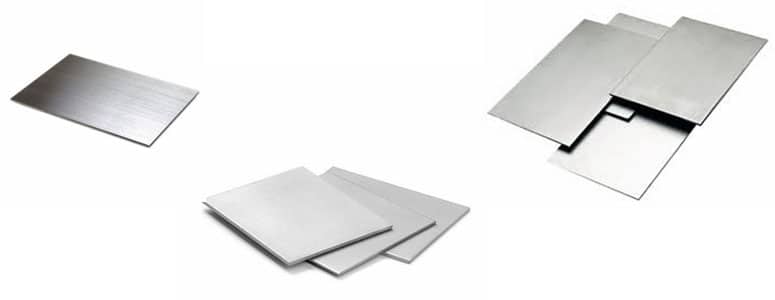
Assuming that the material thickness is 1/4 inch, length is 10 feet, after calculating by the press brake tonnage formula, air bending force requires 165 tons, and some forming workpiece require at least bending force 600 tons.
If most of the workpieces are 5 feet or shorter, it can be almost halved, which greatly reduces the cost of purchase.
So the length of the workpiece is very important for determining the specifications of the new machine. In the same way, the thickness of workpiece also plays the significant role in the hydraulic metal press brake tonnage calculation.
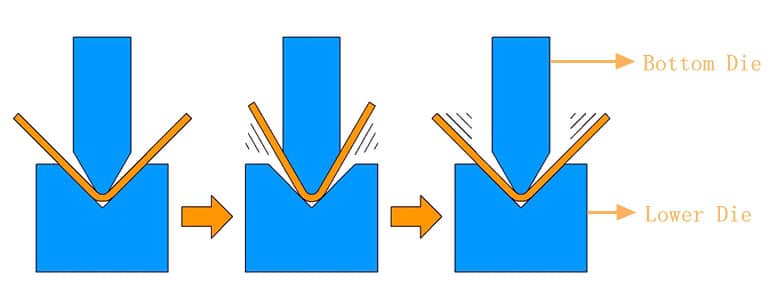
The punch (also called the upper die) of the bending machine is an important part of the bending machine die, responsible for transmitting force to the material to complete the bending operation. The design and selection of the upper die directly affect the quality, accuracy, and appearance of the workpiece. According to different bending requirements, the upper die has a variety of shapes and types, each with its own unique purpose. Now all different kinds press brake machines are designed to bend to a certain proportion of force capacity.
From the press brake tonnage chart, the force capacity is designed according to the ratio of bottom die and sheet or plate thickness: 8-to-1. Usually we can get a good bending effect based on this ratio.
However, this ratio is not fixed.
– For thin material, we can use the ratio of 6-to-1.
– But when we are forming thick material, we can choose the bottom die V groove and material thickness ratio of 10-to-1 or 12-to-1, which can reduce press brake force capacity, and also can get the perfect bending effect.
The upper die of the bending machine is usually a metal bar or strip tool installed on the upper beam of the bending machine. When bending, the upper die moves downward and cooperates with the lower die (usually a V-groove) to force the sheet to bend to the desired angle and shape.
The basic features of a typical upper die include:
- Die shape:
The shape of the die determines the shape of the bend. Common upper die shapes include straight knives, sharp-angle knives, rounded-angle knives, etc.
- Die angle:
The angle of the upper die is generally 88° or 90°, which is used for standard 90-degree bending. For non-90-degree bending operations, there are also special upper dies.
- Material:
The upper die is usually made of hardened steel to withstand heavy loads and long-term use.
Depending on the bending requirements, there are various types of upper dies for press brakes, mainly the following:
- Straight knife (flat head upper die)
Features: The straight knife upper die has a straight blade, which is suitable for standard 90-degree bending or larger bending operations on materials.
Application: It is used for conventional 90-degree bending and some specific larger-angle bending, and is widely used in daily production.
- Sharp-angle punch
Features: The blade of the sharp-angle knife upper die is sharp (less than 90°), which is used for sharp bending operations less than 90 degrees.
Application: It is suitable for precision bending of thin plates, especially in situations where sharp bending is required, such as making V-grooves, U-grooves or some special structural parts.
- Rounded upper die
Features: The blade of the rounded upper die is circular, which is suitable for bending operations with a certain bending radius.
Application: Used for workpieces that require a larger bending radius, such as aluminum and copper parts, to avoid cracks or fatigue damage to the material during bending.
- Gooseneck punch
Features: The shape of the gooseneck punch is like a reverse "S" shape, designed to prevent the punch from interfering with the already formed part.
Application: Suitable for complex workpieces or operations that require multi-step bending, especially for secondary or multiple bending of already formed parts.
- Multifunctional punch
Features: This punch has adjustable angles and replaceable cutter heads to adapt to bending at various angles.
Application: Suitable for small batch and multi-variety bending operations, which can reduce the frequency of changing the die and improve production efficiency.
In some specific processing requirements, the punch may have some special designs to meet more complex bending requirements:
- Segment punch
The punch can be designed as a segmented structure, allowing multiple small segments of the punch to be combined and used together. This design is easy to adjust and combine according to the specific shape and size of the workpiece, and is particularly suitable for the production of small batches or variable parts.
- Upper and lower die matching accuracy
The precision matching between the upper die and the lower die is very important, especially in high-precision bending operations. The upper die head and the V-groove of the lower die must be precisely aligned to ensure the accuracy of the bending angle and shape.
- Anti-indentation upper die
In some high-demand workpiece processing, in order to avoid indentations on the material surface, an upper die with a special coating or smooth surface can be selected. This can reduce the surface damage of the workpiece while maintaining the bending strength.
The bending force depends not only on the thickness and tensile strength of the material, but also on the shape of the upper die. Generally, the sharper the upper die head, the smaller the contact area, and the greater the force required for bending. The blunter or rounder the upper die head, the smaller the required bending force. Therefore, choosing a suitable upper die shape helps to reduce the bending force and improve the bending efficiency.
After long-term use, the upper die of the press brake machine may be worn due to high-intensity bending operations. In order to extend the service life of the upper die, regular maintenance and care are very important.
- Regular cleaning
The upper die is prone to accumulate metal chips or oil during use, which will affect the accuracy of bending. Therefore, it is very important to regularly clean the surface of the upper die and keep it smooth.
- Anti-rust treatment
Especially for steel upper dies, anti-rust treatment can effectively extend its service life. Usually, a layer of anti-rust oil can be applied before storage to prevent moisture in the air from corroding the surface of the upper die.
- Regularly check wear and tear
During the use of the upper die, the blade may become blunt or produce tiny cracks due to frequent use. Regularly check the wear of the upper die and repair or replace it when necessary to ensure the stability of the bending quality.
The punch upper die of the press brake bending machine is a key component in the bending process. Reasonable selection of the upper die can not only improve the bending efficiency, but also ensure the accuracy and surface quality of the finished product. Factors such as the type, angle, bending radius, and material thickness of the upper die need to be considered comprehensively to meet different bending needs. Regular maintenance of the upper die and maintaining its accuracy are also important steps to ensure the smooth progress of the bending process.
Click here to know:
How to Choose Press Brake Tooling and V Die?
The opening size of the lower die of the bending machine (the opening width of the V-groove) is a very important parameter in the bending process. It directly affects the size of the bending force, the bending accuracy and the quality of the finished product. Choosing the appropriate lower die opening size can ensure the forming quality of the workpiece during the bending process, and can also reduce the force required for bending.
The lower die opening size refers to the width of the V-groove opening of the bending machine, usually represented by the letters V or W. Choosing the correct lower die opening size is one of the key links in the bending process, because it directly affects the contact area and bending radius during the bending process.
The lower die opening size is usually determined according to the thickness t of the plate. In actual production, the basic principle for selecting the lower die opening size is that the lower die opening width is 6 to 12 times the thickness of the plate.
The common selection range is as follows:
- For thin plates (1-3 mm thickness), a lower die opening size of 8 times the plate thickness is usually selected.
- For medium-thick plates (3-12 mm), a lower die opening size of 10 times the plate thickness is usually selected.
- For thick plates (above 12 mm), the lower die opening size is usually selected to be 12 times the plate thickness.
Plate thickness (mm) | Lower die opening size (mm) |
1.0 | 6 - 8 |
2.0 | 12 - 16 |
3.0 | 16 - 20 |
4.0 | 24 - 32 |
6.0 | 32 - 48 |
8.0 | 40 - 64 |
10.0 | 50 - 80 |
12.0 | 60 - 96 |
16.0 | 80 - 128 |
The selection of the lower die opening size is not only related to the thickness of the sheet, but also to the following factors:
- Type of material
Low carbon steel: Standard multiples (8 to 12 times) are usually used.
Stainless steel: Since stainless steel is harder, a larger opening size is usually selected, such as 12 times the thickness.
Aluminum: Aluminum is softer and the opening size can be smaller, such as 6 to 8 times the thickness.
- Bending angle
If the bending angle is 90°, the standard lower die opening size can be used.
If a larger bending angle is required (for example, greater than 90°), the lower die opening size needs to be slightly increased to avoid excessive deformation of the material during the bending process.
For sharp bends less than 90°, a smaller lower die opening can be selected to ensure sufficient forming accuracy.
- Bending radius
During the bending process, the larger the opening size, the larger the bending radius; the smaller the opening, the smaller the bending radius. In order to avoid cracking of the material during the bending process, an appropriate bending radius is usually selected to control the forming accuracy.
- Bending force
The larger the lower die opening size, the larger the contact area, and the lower the force required for bending. Conversely, the smaller the opening, the greater the bending force required. Therefore, when selecting the lower die opening size, the tonnage of the bending machine needs to be considered.
Press Brake Bending Machine Latest Buying Guide
According to the plate thickness t and the specific requirements of the bending, the following steps can be used to determine the optimal lower die opening size.
Select multiples according to material thickness:
- Thin plate: 6-8 times the plate thickness.
- Medium thickness: 8-10 times the plate thickness.
- Thick plate: 10-12 times the plate thickness.
Adjust according to the type of material:
- For hard materials (such as stainless steel), choose a larger opening.
- For soft materials (such as aluminum), choose a smaller opening.
Consider the bending angle and bending radius:
- If sharp angle bending is required, choose a smaller lower die opening.
- If a large bending radius is required, a larger opening can be appropriately selected.
Tonnage of bending press machine:
Make sure that the selected lower die opening does not exceed the load capacity of the bending machine, especially for thick plates with large openings, which require greater bending force.
The lower die opening size is inversely proportional to the bending force. The larger the opening, the smaller the required bending force. For example, if you need to bend a low-carbon steel plate with a thickness of 6 mm, and choose a lower die opening of 40 mm, the required bending force will be less than the bending force when the opening is 30 mm.
The reasonable selection of the lower die opening size is crucial to the bending process, affecting the precision of the finished product, the bending force and the service life of the bending equipment. Correctly selecting the lower die opening size can improve processing efficiency, reduce losses and ensure the quality of the finished product.
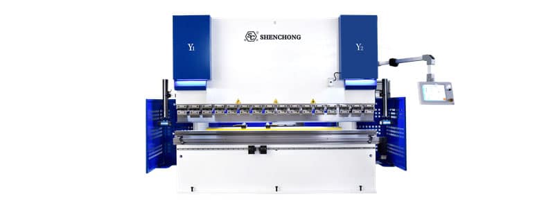
Hybrid Servo CNC Press Brake For Sale
The air bending is the movement of the punch displacement, and penetration into the bottom V die.
If the surface of the material is clean and not lubricated, the friction will be greater when bending. If there is oil on the surface of the material or lubricant is used, the friction will be reduced, which will reduce the bending force, but the reduced friction will also increase the amount of material springback.
The time of bending movement also will influence the press brake tonnage. When the bending speed increases, the tonnage decreases.
The friction coefficient changes with the bending speed. Increasing the bending speed can reduce the friction coefficient and bending force, but it will also increase the rebound of the material.
When air bending, the bending radius is 0.156 times the opening distance of the bottom die. During the air bending process, the opending distance of the bottom die should be 8 times the material thickness.
For example, when we choose 12mm opening distance for bend carbon steel 1.5mm, the bending radius of the workpiece is about 1.9mm. If the bending radius almost as small as the material thickness, it is necessary to form the bottom bending, However, the bottom bending required pressure is about 4 times larger then the air bending.
When the bending radius is larger than the material thickness, the air bending method can be used directly, we can select the suitable lowest bending machine tonnage. When the bending radius is large, it often does not affect the workpiece quality and future use.
Click here to know:
Relationship: Press Brake Radius, Thickness and V Die
To make sure your press brake machine safely within tonnage limits, please review with our Shenchong sales or Shenchong sales engineer when you need calculate a new press brake tonnage.