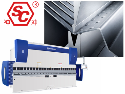
We will do deep research on the metal plate bending forming process to analyze in detail the objective factors that affect the press brake bending quality. And explain the causes of quality problems during operation and propose solutions. This article will guide and summarize the bending process of sheet metal parts.
Sheet metal bending process is widely used in aerospace, automobile, electronics, railway, locomotive, engineering machinery and other fields. Metal plate bending is a key process in the forming of most parts. So the bending quality directly affects the final shape and performance of the product.
There are many factors that affect sheet metal bending, such as the accuracy of the unfolded size of parts, the selection of dies and the rationality of bending sequence. Therefore, the study of plate bending must be analyzed from these factors one by one. Only by studying how to control the bending quality can the overall improvement of the workpiece product be achieved.

When the sheet metal plate is bent, the outer layer of the fillet area is stretched and the inner layer is compressed. When the material thickness is fixed, the smaller the bend fillet, the greater the tensile and compression ratio of the material.
When the tensile stress of the outer fillet exceeds the ultimate strength of the material, cracks or fractures will occur. Therefore, the structural design of the bending workpiece should avoid too small bending fillet radius.
The minimum bending fillet radius of the bending part is related to the mechanical properties, surface quality, hardening degree and fiber direction of the material. The minimum bending fillet radius is only used when the product design requires it. Generally, the metal plate bending inner fillet is equal to or slightly less than the sheet thickness.
To ensure the accurate bending size of the product, determining the unfolding length of the sheet is the primary factor.
Because the outer layer of the sheet metal is stretched longer and the inner layer is compressed shorter during bending, only the length of the neutral layer remains unchanged.
In theory, the length of the neutral layer is equal to the material length. In fact, due to the different materials and hardness of the same thickness of sheet metal, the tensile deformation of the material with high hardness during bending is small, and the neutral layer is outside.
The material with small hardness has large tensile deformation, and the neutral layer is close to the inside. Therefore, the bending coefficient is needed to correct when calculating the length of the unfolded material.
In addition to the sheet material, the thickness of the sheet, the bending angle and the shape of the die have an impact on the bending coefficient. Due to the influence of various factors mentioned above, the calculation of bending coefficient is difficult. At present, some 3D software is mainly used to calculate the bending factor of sheet metal, which is consistent with the metal plate bending factor.
For the pre-machined blank, if the hole is in the bending deformation zone during bending, the shape of the hole will be stretched and deformed after bending. At the same time, it will also affect the size of the parts after bending.
In order to avoid the hole position being distributed in the bending deformation zone, the hole edge distance b (the nearest distance from the outside edge to the hole edge after bending) shall be ≥ 3 times the plate thickness. For elliptical holes parallel to the bending curve, in order to ensure the bending accuracy and prevent hole position deformation, the hole edge distance should generally be ≥ 4 times the plate thickness.
If the hole position must be distributed in the deformation area, in order to ensure accuracy, small holes are generally processed first. The method of reaming after bending meets the requirements. The process hole or notch can also be punched at the bending position to transfer the deformation zone.
For 90 ° bending, in order to facilitate forming, the height of the right angle edge of the workpiece (h) shall not be less than 2 times the plate thickness (t). If the straight edge height of the bending part is required to be h < 2t, increase the height of the bending edge at first. After bending and forming, it can be processed to the required size. Alternatively, a V grroving machine can be used to process shallow grooves in the bending deformation zone before bending.
For metal plate bending parts with oblique angles at the bending side (that is, when the bending deformation area is on the oblique line), due to the low straight line height at the end of the oblique line, the workpiece will be deformed after bending. Therefore, the minimum height of the bending side should meet h > 2t. Otherwise, the straight edge height of the bending part should be increased or the part structure should be changed.
Sheet Metal Forming: What Factors Cause Workpiece Deformation?
When determining the bending direction, we should try to make the blanking fracture zone of the plate at the inner side of the bending part. Thus, the microcracks in the fracture zone can be prevented from expanding into cracks under the action of external tensile stress.
If it is necessary to bend in both directions due to the structure of the part, the bending radius shall be increased as much as possible or other technological measures shall be taken.
The fiber direction of the sheet also has some influence on the bending deformation, especially for the materials with poor plasticity. If allowed, the bending curve of the workpiece should be perpendicular to the fiber direction of the sheet. Otherwise, when the bending curve is parallel to the fiber direction, cracks are easy to form outside the bending part. If it is necessary to bend in multiple directions, the bending curve should be at a certain angle with the fiber direction.

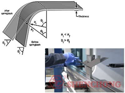
Metal plate bending rebound refers to the phenomenon that the shape and size of the workpiece change after it leaves the mold due to the plastic deformation of the sheet metal.
The degree of springback is usually expressed by the difference between the actual bending angle of the workpiece after bending and the bending angle of the mold, that is, the size of the springback angle.
The factors affecting springback include the mechanical properties of the material, the relative bending radius, the shape of the workpiece, the die gap and the pressure during bending. Because there are many factors affecting springback, theoretical analysis and calculation are complex. In general, the larger the ratio of the radius of the inner fillet to the thickness of the plate, the greater the springback.
At present, it is mainly through the mold manufacturer to take certain measures to reduce the springback when designing the mold, such as the reserved springback angle of the lower mold, the use of 88 ° or 86 ° V-shaped angle, etc. Or increase the correction pressure when bending.

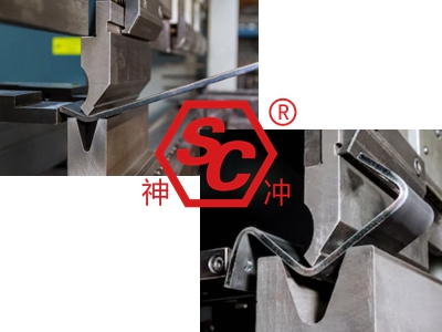
The selection of the upper die is determined by the shape of the workpiece. Because there is no interference between the die and the workpiece during the bending process. For example, in U-shaped bending, the appropriate upper die should be selected according to the size ratio of the three sides.
Generally, if the size of the bottom edge is greater than or equal to the other two right-angle edges, the upper die is used for the optional frame. If the bottom edge is smaller than the other two sides, the gooseneck upper mold shall be selected.
In order to prevent the interference between the part and the die during metal plate bending, resulting in the deformation or scrap of the part, the numerical control system can be used to simulate the bending of the workpiece to detect whether the die is suitable for the bending and forming process of the workpiece.
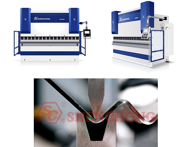
The fillet radius of the workpiece is mainly determined by the V-groove width of the lower die, while the fillet radius R of the upper die also has some influence.
The fillet radius R of the upper die is generally the same as or slightly smaller than the plate thickness. When folding hard aluminum plate and other parts with poor plasticity, in order to prevent fracture or crack, the upper and lower dies with larger fillet radius and V-groove size should be selected. At the same time, anti-crack grooves are designed at both ends of the bending line of the fittings.
In addition to the 90 ° upper mold, when bending stainless steel plate, aluminum plate or medium-thick plate with large amount of rebound, the 86 ° and 88 ° upper mold can be selected according to the size of material rebound. At the same time, the lower die with the same angle should be selected to match it.

The selection of V-groove width is mainly based on the plate thickness. The larger the width of the V-groove, the smaller the bending pressure required. In general, V=6t is usually taken for the thinner sheet, where V is the width of the V-shaped groove of the lower die, and t is the plate thickness.
See the table below for the selection of V-groove width and plate thickness of common lower die.
Plate Thickness t/mm | V-groove Width |
0.5~2.6 | 6t |
3~8 | 8t |
9~10 | 10t |
In addition, the bending size of the part should also be considered. When the size is small, if the width of the V-shaped groove of the lower die is large, the top of the sheet cannot contact with both sides of the V-shaped groove at the same time when bending. And it will slide into the V-shaped groove, resulting in failure to form.
What is Sheet Metal V Groove Bending Process?
The lower mold is generally divided into single groove and double groove.
The single-slot lower die is flexible and convenient to use. The double-groove lower mold has good stability. We should determine the applicable lower mold according to the actual situation.
In addition, there are some special lower molds. For example, the segment differential die, the blank holder flat die and the elastic rubber lower die with circular arc.
The V-shaped groove is divided into right angle lower die and acute angle lower die according to the angle.
The common angles of the sharp angle lower die are 30 ° and 45 °. The commonly used angles of right-angle lower die are 88 ° and 90 °. The standard lower die angle is 88 °.
The selection is determined according to the nature of the material and the amount of rebound. When the tensile strength of the material is large and the rebound amount is large, such as stainless steel or thinner sheet metal, the 88 ° lower die shall be selected. The lower die of 90 ° can be selected for soft materials such as ordinary low carbon steel and copper.
The factors affecting rebound are analyzed as follows:
- Related to material properties. Under the condition of the same mold and the same material thickness, the size of rebound is ranked as SUS>Al>SPCC.
- Under the same mold and material conditions, the springback of thin plate is greater than that of thick plate.
- When bending with the same material, the larger inner arc radius R, the larger rebound amount.
- The greater the bending pressure, the smaller the springback.
If possible, the workpiece should be bent at the symmetrical position of the machine axis as far as possible. This operation has higher precision than workpiece offset bending. In addition, this can avoid the adverse effects on the machine due to eccentric load. If offset bending is really needed, it is recommended that the bending tonnage should not exceed 30% of the total tonnage.
- Cause 1:
The expanded size of the sheet is not accurate.
- Measure 1:
Adjust the bending factor and recalculate the unfolded dimension.
- Cause 2:
The positioning dimension is not accurate.
- Measure 2:
Adjust the backgauge.
- Cause 3:
Cumulative error during multiple bends.
- Measure 3:
Select a reasonable positioning datum to eliminate accumulated error.
- Cause 1:
The pressure is not appropriate.
- Measure 1:
Adjust the pressure.
- Cause 2:
Wrong material parameter selection.
- Measure 2:
Adjust parameters.
- Cause 3:
The width of the V-shaped groove of the lower die is not appropriate.
- Measure 3:
Select appropriate V-groove width.
-Cause 1:
The height of the press brake upper and lower dies is inconsistent.
- Measure 1:
Adjust the wedge height.
- Cause 2:
Die wear is inconsistent.
- Measure 2:
Adjust the mold.
- Cause 1:
The distance between the back gauge and the mold center is inconsistent.
- Measure 1:
Adjust the position of the press brake backgauge.
- Cause 2:
The plate is twisted and deformed.
- Measure 2:
Correct material deformation.
- Cause 1:
The type of bending machine is not appropriate.
- Measure 1:
Select the appropriate metal plate bending machine.
- Cause 2:
The bending die does not fit.
- Measure 2:
Reconfigure the appropriate mold.
- Cause 3:
The bending sequence is unreasonable.
- Measure 3:
Change the bend order.
- Cause 4:
The design of workpiece structure is unreasonable.
- Measure 4:
Adjust the structural design.
- Cause 1:
The internal radius of bending is too small.
- Measure 1:
Select the upper die with larger fillet radius R.
- Cause 2:
The fiber direction of the plate is parallel to the bending curve.
- Measure 2:
Change the discharging direction of the workpiece during blanking.
- Cause 3:
The burr surface of the plate is outside the bending angle.
- Measure 3:
The burr is changed to the inside of the bent part or the burr is polished.
- Cause 4:
The material has poor plasticity.
- Measure 4:
Design anti-crack holes at both ends of the bending line. Select materials with good plasticity or annealing treatment.